
The diagram above shows a battery, a switch and a bell. The switch might be nothing more that a push-button switch. The switch is shown "open", and the bell would not be ringing. If the switch were "closed", the bell would ring. Just in case you are not yet clear what you are looking at, I'll add: The circuit above would lousy for a burglar or fire alarm. It would be good for a doorbell! I wanted a simple starting point for this help file.
The diagram shows the "alarm system" in a "no event" state, there is no fire, there is no intruder.
To make our rather sad circuit into a usable (though still poor) alarm system, we need to use something "clever" for the switch. Here's where you can spend money, or have fun, or both.
You can buy devices which are switches, but which are "switched on" (closed) not by your finger, but by the presence of fire or of a burglar. Or you can make something that delivers the same function.... but we're not going to go down that path.
For a burglar alarm, it is too susceptible to a burglar, upon tripping the alarm simply re-opening the switch, and turning the bell off again.
For a fire alarm, it is unnecessarily unreliable. More on this in a moment.
To thwart the burglar, we are going to want a latching circuit. Once the bell starts ringing, it should continue ringing even if the wires around the switch are torn off the wall and destroyed... or, alternatively, connected together. One or the other will turn off some crude alarm systems. Accomplishing the latching is a topic for another time, or for achieving by the general techniques addressed elsewhere in these sensing and control tutorials. (See, for instance, the pages on programming the systems.)
The page you are reading now concentrates on how the sensors should be hooked up.
The "unnecessary unreliability" of the system is an area which has led to the following answers and traditions in the world of alarm systems.
Many burglar and fire detectors are, essentially, switches.
Traditionally, fire-detecting switches open when they "see" no fire, and close when they "see" fire. And, somewhat surprisingly?, burglar-detecting switches operate the other way around.
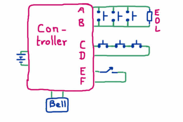
The following shows a fancier alarm system than the one we saw before. It uses traditional detectors. The system is shown with no fire, no burglar detected, i.e. with the switches all in their "no event" states. (If you are the least bit unfamiliar with the switch symbols used, take a quick peek at my little aside about switch symbols. Clicking that link will open the information in a new window or tab... you won't lose the page you are reading now.)
Wow! Our "simple" little alarm system has grown a bit!
The details of the controller are beyond the scope of this page. The point of the above is to allow me to tell you about how fire and burglar detectors are traditionally connected to alarms. The sort of sensors used in the above are the sort you will be able to buy easily.
Fire sensors tend to be switches that close when fire is detected. Some are momentary, and others close for good if they get hot, and have to be replaced after doing their job. Burglar sensors tend to open when an intruder is detected. There is a method to this madness, but I will defer that discussion. First let's just look at how it works.
The fire sensors, the once connected to "A" and "B". Imagine for a moment there is nothing at the end of the loop, that there is no resistor marked "EOL". The controller will attempt to send electricity from A, across on of the "rungs" of the ladder of open (while they are cold) fire sensing switches, and back, somehow, to B. As long as there is no EOL resistor, the rule is simple: If no electricity is able to get around the A-B loop, then there is no fire.
Now consider the "C-D" loop. That shows three normally closed intruder detectors. As drawn, electricity will flow around that loop, and the controller should interpret that as "no intruder".
The switch connected to E and F is the "turn on the burglar alarm" switch. The controller will only "look" at the burglar sensors if the switch is closed. (Presumably, the fire alarm function should always be "on".)
So far, so good, I hope.
We're now going to return to the fire detectors loop, loop A-B, and consider the situation when the EOL resistor is present, as shown.
"EOL" stands for "end of line". Having an EOL resistor in place means you need a slightly more complicated controller. Now the rules are....
"Trouble" is a warning to the system's owner that all is not well. It is unlikely that there is a fire.... but it is probable that if there were to be a fire, then the alarm would not ring as it should.
The point of the EOL resistor, and the extra work creating the more complex controller, was to guard against the very real possibility that, over the years, something will happen to cause a break in the wiring of loop A-B. You would never know it was there, otherwise, would you... until you had a fire and the alarm didn't go off.
This isn't just a theoretical "good idea". It is used in any decent fire alarm system. I, personally, was saved from relying on a "dead" fire alarm system which would not have reported a fire. A "trouble" signal alerted me to a problem in the wiring of the alarm in my home. (A racoon had chewed through the wires.)
Having the circuit protected like this is called having a "supervised" circuit. A diode is sometimes used instead of a resistor at the end of the line.... a zener diode, usually, I think. Anything that lets some current flow, but less current than one of the fire detectors would pass, will do.
Why are fire sensors normally open, and burglar sensors normally closed? Partly from "we've always done it that way", I suspect, but also because each has it's pros and cons, and each is meeting a different need.
The burglar-detecting loop, sensors connected "in series", can always carry a current, and can always trigger an alarm if the loop is broken because is something is wrong... be it an actual intruder or troublesome wiring, you need to treat it as a possible intruder. You don't NEED the more complex possibilities of the other system.
Two things can be understood by reference to the following....
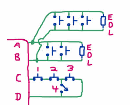
1) It is NOT a good idea to add an additional "ladder" of fire sensors, as shown above. If you need, say, to have a set on the first floor of your house, and a second set on the second floor, you should still, as far as the "logic" of the thing is concerned just have one "ladder". That doesn't stop you from having sensors on more than one floor. Just don't be tempted to "add on" bits the way it was done in the diagram.
2) You may add a switch, like the one marked "4" to the burglar alarm sensor string. It would want to be a non-momentary "on/off" switch. Can you see what it would do?
When switch 4 is closed, even if the system is "armed", and "looking" for intruders, it will not "see" switch 3 open.
Such a switch (switch 4) could be useful. It lets you bypass, or "disconnect" some sections of the system. For example, you might want to be able to monitor just the downstairs motion detectors (numbers 1 and 2) in your home when you are there, but upstairs in bed. At that time, you wouldn't want the motion detector in the upstairs hall active. (number 3). On the other hand, when the house was empty, you would open switch 4, and all of the sensors would be monitored.
3) (not fully illustrated)... You make things difficult for burglars... and halve the cost to the wire you use... if just one wire goes out from the controller at "C", and then one wire comes back to "D" by a (mostly) different route. If a burglar can, thought a broken window, say, get at places similar to the two points where switch "4" attaches, the burglar can bypass parts of the sensor string, can't he/ she?
Once you learn that most fire detectors are open switches when cold, and most burglar detecting switches are closed when no intruder is "seen", you have the facts you need. The rest of the material here is common sense, or things you could work out for yourself. What fun is a project with no scope for your ingenuity? However, I hope that being given some of the ideas above was welcome?
![]() Page tested for compliance with INDUSTRY (not MS-only) standards, using the free, publicly accessible validator at validator.w3.org
Page tested for compliance with INDUSTRY (not MS-only) standards, using the free, publicly accessible validator at validator.w3.org